中国激光, 2021, 48 (2): 0202003, 网络出版: 2021-01-07
空间整形飞秒激光加工金属微细槽实验研究  下载: 2373次特邀研究论文
Spatially-Shaped Femtosecond Laser Manufacturing of Microgrooves in Metals
图 & 表
图 1. 基于SLM的飞秒激光空间整形光路装置图
Fig. 1. Optical path device diagram of femtosecond laser spatial-shaping based on SLM
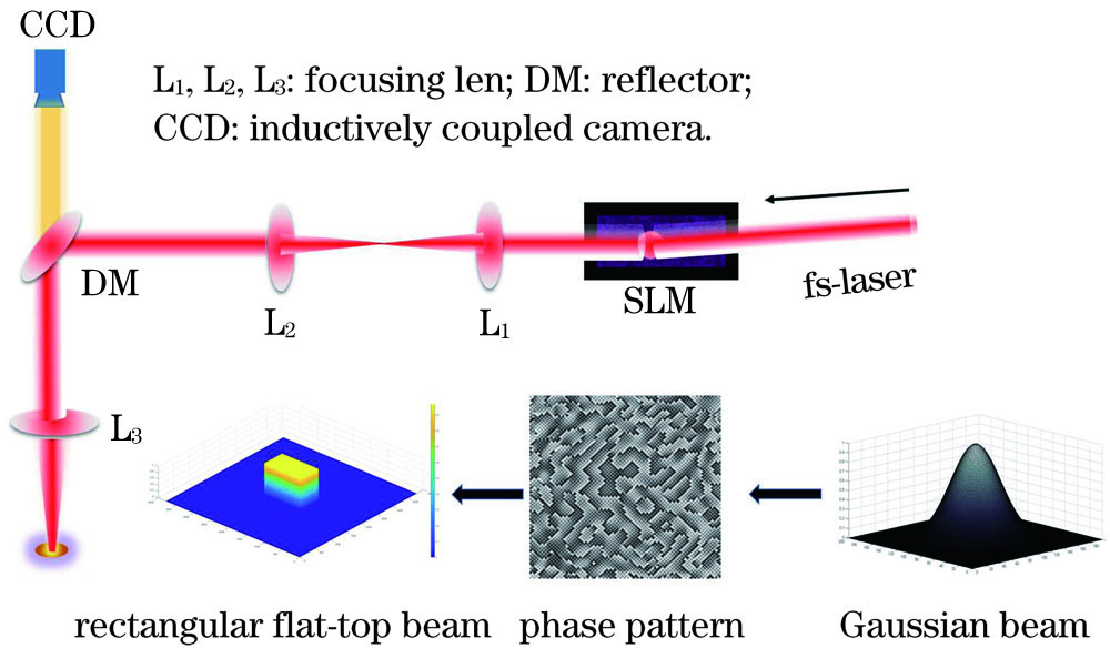
图 2. 矩形平顶光的仿真示意图与灰度图。(a) 矩形光斑仿真示意图;(b)利用迭代算法得到的灰度图
Fig. 2. Simulation diagram of rectangular flat-top beam and grayscale image. (a) Simulation diagram of a rectangular spot; (b) grayscale image obtained by an iterative algorithm

图 3. 整形后的光斑表征及脉冲打点表征。(a)光束质量分析仪测得的矩形平顶光光斑分布; (b) 20个脉冲下的高温合金表面加工形貌;(c) 100个脉冲下的高温合金表面加工形貌;(d) 500个脉冲下的高温合金表面加工形貌
Fig. 3. Characterization of light spot and pulse dot after shaping. (a) Light spot distribution of rectangular flat-top light measured by a beam quality profiler; (b) morphological image of surface with 20 pulses flat-top light ablation; (c) morphological image of surface with 100 pulses flat-top light ablation; (d) morphological image of surface with 500 pulses flat-top light ablation

图 4. 采用高斯光和平顶光加工的微细槽阵列对比。 (a)采用高斯光加工的微细槽阵列形貌;(b) 采用平顶光加工的微细槽阵列形貌;(c) 采用高斯光扫描100次加工的单个微细槽截面轮廓;(d)采用平顶光扫描100次加工的单个微细槽截面轮廓;(e)微细槽阵列的深度与斜度的变化关系
Fig. 4. Comparison of microgroove array processed by Gaussian beam and flat-top beam. (a) SEM image of microgroove array fabricated by Gaussian beam; (b) SEM image of microgroove array fabricated by flat-top beam; (c) cross-sectional profile of a single microgroove (100 scanning times) fabricated by Gaussian beam; (d) cross-sectional profile of a single microgroove (100 scanning times) fabricated by flat-top beam; (e) relationship between the depth and the slope of the microgroove arrays

图 5. 矩形平顶光在不同扫描速度下加工的微细槽对比
Fig. 5. Comparison of microgrooves fabricated by flat-top beam at different scanning speeds

图 6. 不同脉冲能量下微细槽深度和微细槽壁斜度的变化情况。(a)微细槽深度随扫描次数的变化情况;(b) 微细槽壁斜度随深度和扫描次数的变化情况
Fig. 6. Variation of depth and slope of microgrooves under different pulse energies. (a) Depth of microgrooves changed with scanning times; (b) slope of microgrooves changed with microgroove depth and scanning times

图 7. 采用空间整形光束加工的变宽度微细槽阵列。(a)变宽度微细槽阵列的表面形貌图; (b)微细槽阵列截面轮廓图
Fig. 7. Microgroove arrays with variable width processed by spatially shaped beam. (a) Surface morphology of the microgroove array; (b) cross-sectional profile of microgroove array

图 8. 加工宽度为10μm和20μm的微细槽形貌图
Fig. 8. Topographies of microgrooves with width of 10μm and 20μm

图 9. 宽度为150μm的微细槽形貌图。(a) SEM图;(b)白光干涉三维图;(c)横截面轮廓图
Fig. 9. Topography of microgroove with width of 150μm. (a) SEM image; (b) three-dimensional white light interference image; (c) cross-sectional profile view

图 10. 微细槽侧壁边缘元素分布及信号强度变化。(a)微细槽侧壁截面的SEM形貌图;(b)元素信号强度的横向分布;(c) O元素在横向面的分布;(d) Ni元素在横向面的分布;(e) Fe元素在横向面的分布
Fig. 10. Distribution and intensity changes of elements at the processing edge of microgroove. (a) SEM image of the microgroove side wall section; (b) transverse distribution of element intensity; (c) distribution of O element in the transverse plane; (d) distribution of Ni element in the transverse plane; (e) distribution of Fe element in the transverse plane

表 1现有激光加工微细槽情况小结
Table1. Summary of existing laser microgroove processing
|
梁密生, 李欣, 王猛猛, 原永玖, 陈孝喆, 许晨阳, 左佩. 空间整形飞秒激光加工金属微细槽实验研究[J]. 中国激光, 2021, 48(2): 0202003. Misheng Liang, Xin Li, Mengmeng Wang, Yongjiu Yuan, Xiaozhe Chen, Chenyang Xu, Pei Zuo. Spatially-Shaped Femtosecond Laser Manufacturing of Microgrooves in Metals[J]. Chinese Journal of Lasers, 2021, 48(2): 0202003.


 PDF全文
PDF全文

