Photonics Research, 2020, 8 (4): 04000539, Published Online: Mar. 30, 2020
Wide-field ophthalmic space-division multiplexing optical coherence tomography  Download: 526次
Figures & Tables
Fig. 1. (a) Schematic for the ophthalmic SDM-OCT system. BOA, booster optical amplifier; FBG, fiber Bragg grating; MZI, Mach–Zehnder interferometer; PD, balanced photodetector. (b) Picture of the ophthalmic SDM-OCT prototype in the clinic.
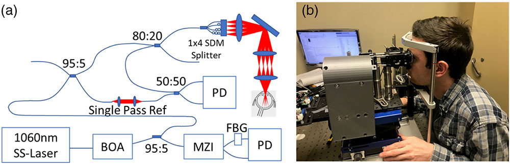
Fig. 2. Geometric considerations for ophthalmic SDM-OCT design. (a) Projection of the curvature of the eye onto the imaging space. (b) Image space separated into four imaging beams with 3 mm optical delay. All four beams fit in the 12 mm image depth. (c) Distance between adjacent beams shows there is no overlapping between adjacent images. (d) Sensitivity roll-off measured over the entire imaging depth range.

Fig. 3. (a) Four-beam raw SDM-OCT image. (b) En face projection of the RPE layer; yellow line shows location of vertical cross section and green line shows location of horizontal cross-section. (c) Vertical cross-section. (d) Horizontal cross-section with some selected anatomical features labeled. CHR, choroid; EZ, ellipsoid zone; ILM, internal limiting membrane; IPL, inner plexiform layer; ONH, optic nerve head; OPL, outer plexiform layer; RPE, retinal pigment epithelium. (e) Retinal thickness map. (f) 3D rendering of stitched SDM-OCT images (also see Visualization 1 ). Scale bars 1 mm.

Fig. 4. SDM-OCT and commercial OCT images from a patient diagnosed with retinal telangiectasia. (a) En face projection SDM-OCT. (b) Vertical cross-section SDM-OCT. (c) Horizontal cross-section SDM-OCT. (d) En face SLO image of commercial system imaging range (5 mm × 3 mm Visualization 2 ). Lateral scale bars 1 mm. Axial scale bars 500 μm for (b), (c), (e), and (f) and 200 μm for (g) and (h).

Fig. 5. SDM-OCT and commercial OCT images from a patient diagnosed with exudative age-related macular degeneration. (a) En face projection of RPE SDM-OCT. (b) Vertical cross-section SDM-OCT. (c) Horizontal cross-section SDM-OCT. (d) En face SLO image of commercial system imaging range. (e) Vertical cross-section commercial OCT. (f) Horizontal cross-section commercial OCT. (g) Zoomed-in ROI from SDM-OCT. (h) Zoomed-in ROI from commercial OCT. (i) Retinal thickness map. Yellow arrow indicates region with retinal thinning. (j) 3D rendering of stitched SDM-OCT images (also see Visualization 3 ). Lateral scale bars 1 mm. Axial scale bars 500 μm for (b), (c), (e), and (f) and 200 μm for (g) and (h).

Fig. 6. SDM-OCT and commercial OCT images from a patient diagnosed with non-proliferative diabetic retinopathy. (a) En face projection SDM-OCT. (b) Vertical cross-section SDM-OCT. (c) Horizontal cross-section SDM-OCT. (d) En face SLO image of commercial system imaging range. (e) Vertical cross-section commercial OCT. (f) Horizontal cross-section commercial OCT. (g) 3D rendering of SDM-OCT image stack (also see Visualization 4 ). (h) Retinal thickness map. (i) En face projection of the outer plexiform layer showing microcysts highlighted by the yellow arrows. (j) Fluorescein angiogram showing matching microcysts to Fig. 5(h) . Lateral scale bars 1 mm. Axial scale bars 500 μm for (b), (c), (e), and (f).

Table1. Comparison of SDM-OCT Systems
|
Jason Jerwick, Yongyang Huang, Zhao Dong, Adrienne Slaudades, Alexander J. Brucker, Chao Zhou. Wide-field ophthalmic space-division multiplexing optical coherence tomography[J]. Photonics Research, 2020, 8(4): 04000539.


 PDF全文
PDF全文

