光学相干域偏振测量技术及其在高精度光纤陀螺器件测量中的应用  下载: 1784次特邀综述
Optical Coherence Domain Polarimetry Technology and Its Application in Measurement for Evaluating Components of High Precision Fiber-Optic Gyroscopes
1 哈尔滨工程大学纤维集成光学教育部重点实验室, 黑龙江 哈尔滨 150001
2 哈尔滨工程大学理学院, 黑龙江 哈尔滨 150001
3 哈尔滨工程大学信息与通信工程学院, 黑龙江 哈尔滨 150001
4 桂林电子科技大学电子工程与自动化学院, 广西 桂林 541004
图 & 表
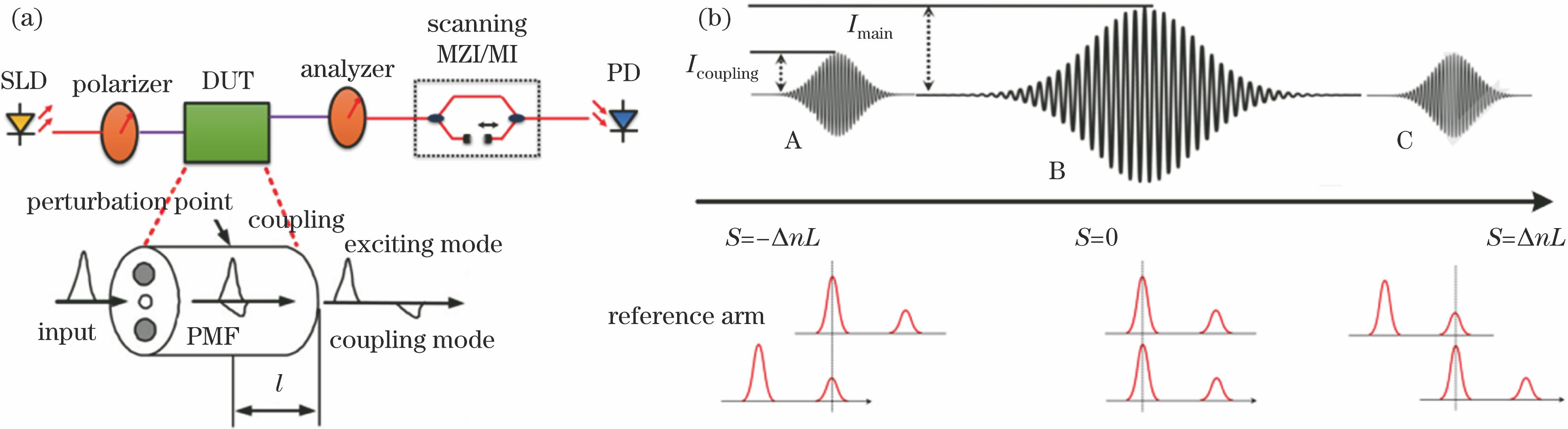
图 1. OCDP技术的原理图。(a) OCDP系统简图;(b) OCDP典型测量结果
Fig. 1. Schematic of OCDP technology. (a) OCDP system; (b) typical result of OCDP system
下载图片 查看原文
图 2. 光程追踪法示意图
Fig. 2. Schematic of optical path tracking method
下载图片 查看原文
图 3. (a)具有功率衰减器的白光干涉仪;(b)信噪比衰减与参考臂光功率的关系
Fig. 3. (a) White light interferometer with power attenuator; (b) relationship between SNR degradation and light power of reference arm
下载图片 查看原文
图 4. (a)平衡探测光路;(b)理论信噪比与耦合器1分光比的关系[34]
Fig. 4. (a) Balanced detection optical path; (b) relationship between theoretical SNR and splitting ratio of coupler 1[34]
下载图片 查看原文
图 5. (a)偏振分束器标定方法原理图;(b)偏振分束器标定法与传统方法结果对比
Fig. 5. (a) Schematic of PBS-calibrated method; (b) comparison between results of PBS-calibrated method and traditional method
下载图片 查看原文
图 6. (a)差分光学延迟线结构;(b)差分结构与单端结构的插入损耗波动对比
Fig. 6. (a) Structure of differential optical delay line; (b) comparison of insertion loss fluctuation between differential structure and single GRIN lens
下载图片 查看原文
图 7. (a)光学延迟线拓展原理图;(b)延迟线拓展后的自校准信号
Fig. 7. (a) Schematic of range extention of optical delay line; (b) self-calibration signals after range extention of optical delay line
下载图片 查看原文
图 8. (a)色散补偿前后的Y波导的典型测试结果;(b)色散测量示意图;(c)色散补偿流程图
Fig. 8. (a) Typical test results of Y waveguide before and after dispersion compensation; (b) schematic of dispersion measurement; (c) flow chart of dispersion compensation
下载图片 查看原文
图 9. (a)闭环色散补偿示意图;待测保偏光纤(b) 945~960 m段与(c) 1950~1980 m段数据对应的判据函数曲面;待测保偏光纤(d) 945~960 m段与(e) 1950~1980 m段原始测量数据(蓝色线)与色散补偿后的数据(红色线)
Fig. 9. (a) Schematic of closed-loop dispersion compensation; criterion function surface corresponding to PMF in range of (b) 945-960 m and (c) 1950-1980 m; original data (blue curve) and its counterpart after dispersion compensation (red curve) corresponding to PMF in range of (d) 945-960 m and (e) 1950-1980 m
下载图片 查看原文
图 10. (a)光纤环测试型与(b) Y波导测试型白光干涉测试系统
Fig. 10. Prototype of white-light interferometric measurement system for (a) fiber coil and (b) Y waveguide
下载图片 查看原文
图 11. (a) Y波导测试方法示意图;(b)典型的Y波导测试结果
Fig. 11. (a) Schmetic of measurement method for Y waveguide; (b) typical test result of Y waveguide
下载图片 查看原文
图 12. (a)超简结构和(b)改进的Y波导双臂同时测试原理图
Fig. 12. Schematics of (a) ultra-simple structure and (b) improved structure for simultaneous measurement of both arms of Y waveguide
下载图片 查看原文
图 13. Y波导芯片基底反射模式的(a)示意图与(b)测试结果
Fig. 13. (a) Schematic and (b) measurement result of reflection modes from substrate of Y waveguide core
下载图片 查看原文
图 14. 长度超过3 km的保偏光纤环的分布式偏振串扰。(a)含有色散的直接测试结果;(b)色散补偿后的测试结果(IPP:迭代相位包方法)
Fig. 14. Distributed polarization crosstalk of PMF coil with length greater than 3 km. (a) Measurement results with dispersion; (b) measurement results after dispersion compensation (IPP method: iterative phase packet method)
下载图片 查看原文
图 15. 光纤环测试结果的傅里叶分析
Fig. 15. Fourier analysis of fiber coil measurement results
下载图片 查看原文
表 1单一微扰点的一段保偏光纤中所有波列的传输时间和幅度
Table1. Transmission time and amplitude of all wave trains for a PMF with one perturbation point
| Path | Transmission time | Normalized amplitude |
|---|
| 1 | tf,MX+tf,XN | cos θ1cos θ2 | | 2 | tf,MX+ts,XN | ρXcos θ1sin θ2 | | 3 | ts,MX+tf,XN | ρXsin θ1cos θ2 | | 4 | ts,MX+ts,XN | sin θ1sin θ2 |
|
查看原文
表 2单一微扰点的一段保偏光纤的干涉组合
Table2. Normalized time-delay difference and amplitude of interferogram for a PMF with one perturbation point
| Wave strain | Wave strain | Time-delaydifference | Normalized crosstalkamplitude |
|---|
| 1' | 1″ | 0 | cos2θ1cos2θ2 | | 2' | | 2″ | cos2θ1sin2θ2 | | 3' | | 3″ | sin2θ1cos2θ2 | | 4' | | 4″ | sin2θ1sin2θ2 | | 1' | 2″ | τXN | ρXcos2θ1cosθ2sinθ2 | | 3' | | 4″ | ρXsin2θ1cosθ2sinθ2 | | 1' | 3″ | τMX | ρXcosθ1sinθ2cos2θ2 | | 2' | | 4″ | ρXcosθ1sinθ2sin2θ2 | | 1' | 4″ | τMX+τXN | cosθ1sinθ2cosθ2sinθ2 | | 2' | 3″ | τMX-τXN | cosθ1sinθ1cosθ2sinθ2 |
|
查看原文
表 3干涉峰的时延差与归一化串扰幅度
Table3. Time-delay difference and normalized crosstalk amplitude of interferogram
| Time-delay difference | Normalized crosstalk amplitude |
|---|
| 0 | 1 | | τXN | ρX |
|
查看原文
表 4本课题组提出的白光干涉测试系统与国外同类仪器性能的对比
Table4. Performance of white-light interferometric measurement system proposed by our subject group comparing with foreign similar instruments
| Country | Organization | Model | Technical configuration | Wavelength/nm | Sensitivity/dB | Dynamic range /dB | Spatial resolution /cm | Measurement length /m (Δn=5×10⁻⁴) | Dispersion compensation function |
|---|
| France | Photonetics Company | WIN-P400 | Bulk optic | 850, 1310 or 1550 | -80 | 80 | 10 | 1600 | None | | USA | General Photonics Company | PXA-1000 | Fiber optic | 1310 or 1550 | -95 | 75 | 5 | 1300 or 2600 | None | | South Korea | FIBERPRO Company | ICD800 | Bulk optic | 1310 or 1550 | -80 | 80 | 10 | 1000 | None | | China | Harbin Engineering University | OCDP-F-SLD | Fiber optic | 1310 or 1550 | -105 | 100 | 8(Full range) | 5000 | Yes |
|
查看原文
杨军, 苑勇贵, 喻张俊, 李寒阳, 侯长波, 张浩亮, 苑立波. 光学相干域偏振测量技术及其在高精度光纤陀螺器件测量中的应用[J]. 光学学报, 2018, 38(3): 0328007. Yang Jun, Yuan Yonggui, Yu Zhangjun, Li Hanyang, Hou Changbo, Zhang Haoliang, Yuan Libo. Optical Coherence Domain Polarimetry Technology and Its Application in Measurement for Evaluating Components of High Precision Fiber-Optic Gyroscopes[J]. Acta Optica Sinica, 2018, 38(3): 0328007.


 PDF全文
PDF全文

